Embedded Programming and Memory
Prelab due 9/22/25 at 1:00 pm
Writeup due 9/29/25 at 1:00 pm
About
In this lab, you will interact directly with the registers for the AMD chip that operates your Arduino. While in previous labs you saw how to use the Arduino API to control input and output on pins, most MCUs do not come with such a useful layer of abstraction. In this lab, you will learn what happens under the hood of this abstraction, by setting bits in MCU control registers yourself. In doing this, you will gain some experience interpreting a datasheet for a device as complex as a microcontroller. In the last part of the lab, you will also get some sense of the memory limits of this microcontoller.
Lab 3 Rubric
Resources
Materials
Included in your kits:
- Arduino Uno R4 and USB cable
- Breadboard
- 1 LED (any color)
- 2 push buttons
- 3 resistors (1 x 1kΩ; 2 x 10kΩ)
- Jumpers/wires
Provided:
- None necessary
Steps
-
Wire up the following circuit. At different steps in the lab, we will work with different parts of the circuit.
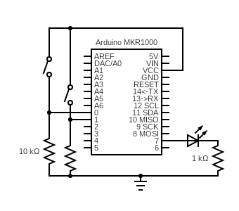
As we move into writing more complex code for the labs, it’s a good idea to have a simple file handy that tests out the circuitry to make sure that it is working as expected. You’ll be asked to write such code for later labs, but we are providing the code for this lab. The onboard LED should light up when one button is held, and the external LED should light up when the other button is held.
void setup() { for (int i = 0; i < 2; i++) { pinMode(2 + i, INPUT); pinMode(12 + i, OUTPUT); } } void loop() { for (int i = 0; i < 2; i++) { if (digitalRead(2 + i)) { digitalWrite(12 + i, HIGH); } else { digitalWrite(12 + i, LOW); } } } -
Copy our starter code for steps 2/3 into a new sketch. In this sketch, you will work with the I/O registers to blink the onboard LED.
-
Fill in the blanks in the code, following the comments. Ignore the commented out code for step 3 for now. The onboard LED is wired to pin 13 of the Arduino.
-
Upload, run, and debug your code. You’ll know it’s working when the onboard LED blinks on for one second and off for one second. If/when you ask a TA for debugging help, the TA will ask you to pull up the debugger (which you learned to do in the prelab) and show you the PmnPFS register (remember the mn corresponds to the RA4M1 pin number, so port 1, pin 1 would be P101PFS). Be ready to talk about what you expect the field values to be.
-
-
Now, you will modify the code to read the input from one of the buttons and use it to drive the LED on when the button is pressed down and off when the button is not pressed.
-
Fill in the TODOs related to step 3 in the code. For the body of the
step3function, you could use anif-expression, but you can also write the code as a single assignment. Look to prelab Q3.1 for a reminder on how to read pin input. -
Change
loopto callstep3instead ofstep2. -
Upload, run, and debug your code, and, when working, get it checked off by a TA.
-
Save the code as
step3.ino(or you can leave it asstep2_3.ino, as long as it’s clear that it has to do with step 3) to be submitted later.
-
-
Create a new sketch from this starter. In this sketch, you will set up an interrupt on Pin 2 to detect the rising edge of the signal, indicating that the button has been pressed. The number of presses will be printed to
Serial.-
Fill in the TODOs, following the comments.
-
Upload, run, and debug your code. If it is not working, carefully check that you configured the registers according to your answers in the prelab, using the debugger.
-
-
In this step, you will enable interrupts on the other button (pin 3). You will write code such that the external LED toggles between on and off whenever the button on D2 is pressed, and the on-board LED toggles between on and off whenever the button on D3 is pressed. Make a new file and:
-
In
setup, using information from the Arduino schematic and the configuration you used in Step 2 of the lab, configure pins 12 and 13 as GPIO outputs. -
In
setup, using the configuration you used in Step 4 of the lab, configure pins 2 and 3 as inputs that trigger an interrupt on the rising edge. You will essentially be duplicating the code you used for pin 2 in step 4 and adapting it to set up pin 3, as well. Because we have two interrupt sources (two pins), we will also have two CPU interrupts. Just use interrupt channel 30 for the second one, e.g.const unsigned int CPU_INT_1 = 31; const unsigned int CPU_INT_2 = 30;Both CPU interrupts should go to the same handler (for example,
ourISR), i.e. your CMSIS function calls should be:NVIC_SetVector((IRQn_Type) CPU_INT_1, (uint32_t) &ourISR); NVIC_SetPriority((IRQn_Type) CPU_INT_1, 14); NVIC_EnableIRQ((IRQn_Type) CPU_INT_1); NVIC_SetVector((IRQn_Type) CPU_INT_2, (uint32_t) &ourISR); NVIC_SetPriority((IRQn_Type) CPU_INT_2, 14); NVIC_EnableIRQ((IRQn_Type) CPU_INT_2); -
In Q4.8 of the prelab, you learned that the MCU sets a flag that can help us track down the source of an interrupt. You cleared this flag without checking it in step 4, because there was only one interrupt source. You can also check this flag to find out the source of the interrupt. One of your pin interrupts will be connected to
CPU_INT_1, and the other pin interrupt will be connected toCPU_INT_2, so you can check the corresponding flag for each CPU interrupt to figure out the source. Once you determine the source, use this information to toggle either the external LED (for the interrupt on pin D2) or the on-board LED (for the interrupt on pin D3). Bit operation hint: you can flip the value of a bit using XOR (^), e.g.1 ^ 1 = 0and0 ^ 1 = 1. Remember to clear the flag and useNVIC_ClearPendingIRQfor the corresponding CPU interrupt when you’re done with the ISR. -
Finish writing your code, and upload, run, and debug it. When it is working, check it off with your TA.
-
Save the code as
step5.inoto be submitted later.
-
-
You can do this last step during lab with your partner, or alone after the lab. This step requires your Arduino but doesn’t require you to build any circuits.
- Create a new sketch and copy in this starter code. For the TODO line, pick your favorite peripheral register and replace the
R_PERIPHERAL->REGexpression with it. Uncomment that line and run the code, making sure to save the output somewhere that all group members can access it. If some of the syntax or keywords look unfamiliar, talk through them or ask a TA – not everyone in the course has taken or remembers their intermediate systems course. The syntax*addrassumes a memory address is stored in the variableaddrand gives you the value stored at that address. Conversely, the syntax&valassumesvalis a variable (or function name, or other piece of data that might exist in memory) of some sort and gives you the address of that piece of data.
Note: if you upload the code and nothing appears on the serial monitor, single-press the reset button on the Arduino.
-
At the very end of the
setup()function, include the following code. Before running it, make a prediction of what will happen.int* corruptLoop = (int*) &loop; *corruptLoop = 32580; // can use any nonsense value Serial.print("corruptLoop: "); Serial.println((unsigned int) corruptLoop, HEX); Serial.print("corruptLoop dereferenced: "); Serial.println(*corruptLoop);Run the code and make note of what happened.
- Create a new sketch and copy in this starter code. For the TODO line, pick your favorite peripheral register and replace the
-
Turn in your work:
-
Save your code from steps 3 and 5. Upload this to the “Lab 3 Code” assignment on Gradescope (include all partner(s) on the submission).
-
INDIVIDUALLY, complete the Lab 3 writeup assignment on Gradescope.
-