Introduction to Arduino
Prelab due 9/8/25 at 1:00 pm
Writeup due 9/15/25 at 1:00 pm
About
This lab introduces you to the Arduino platform and to working with basic circuits. By the end of this lab, you will have been introduced to the Arduino IDE and some basic Arduino programming. You will also have used a circuit diagram to wire up some circuits with LEDs, resistors, and push buttons.
Lab 1 Rubric
Resources
Materials
Included in your kits:
- Arduino UNO R4 WiFi and USB-C cable
- Breadboard
- 3 LEDs (any colors)
- 5 resistors (to be determined by you during the lab)
- 2 push buttons
- Jumpers/wires
Provided:
- None necessary
Steps
-
Install or open the Arduino IDE:
Install the Arduino IDE.
When the IDE is installed, open it. Under the
Board Managermenu, make sureBoardreads Arduino UNO R4 WiFi. If not, use the menu to select it. You might have to use the Boards Manager link in the menu to install the Arduino UNO R4 Boards core. More information on the board manager is here. -
Load your first program onto the Arduino:
-
Under the
File > Examplesmenu in your IDE, open01. Basics > Blink. This opens an example Sketch (Arduino program) calledBlink. Take a moment to read through the code, including the documentation at the top, with your partners. -
Connect your Arduino to a USB drive on your computer using a USB-C cable. You can keep the Arduino in the case it came with for this step.
-
Use the upload button to upload the Sketch to the board. Instructions on how to use the Arduino IDE to upload are here.
Troubleshooting: if you get an error about a device not found on a port, try selecting a different port in the
Tools > Portmenu. If that doesn’t help: make sure there is nothing else plugged in to the ports of your laptop, and try a different port. Once you have a connection, update the firmware of the Arduino (via the Tools menu). -
Observe the on-board LED (near the GND pin) blinking, with the LED toggling between ON and OFF every 1 second.
-
-
Edit the sketch to make the LED blink twice as slowly. Upload the code and verify that the LED is blinking slower.
-
Edit the sketch to make the LED gradually change from blinking slowly, to blinking quickly, and back:
-
Reference the Arduino Language Reference on Structure for the syntax of
forloops,ifstatements, etc. -
Observe that the
loop()function of the sketch will repeat forever. Instead of making afor loopinside this function, use global variable(s) that you initialize in thesetup()function and manipulate in theloop()function, such that you only calldigitalWrite(...)twice during each iteration of theloop()function. -
The delay between toggling the LED on and off should change from 2000 ms to 100 ms and back to 2000 ms in increments of 100ms. Concretely, the LED should be on for 2000 ms, then off for 2000 ms, then on for 1900 ms, then off for 1900ms, then on for 1800 ms, then off for 1800 ms, and so on, counting down to 100 ms, and then counting back up to 2000 ms.
-
Upload, observe, and debug your code.
-
-
Run the same code using an external LED, by connecting your first circuit on the breadboard:
-
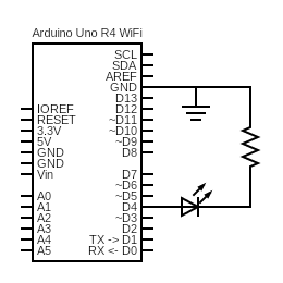
You will connect a physical LED to the UNO R4. Study the pin labels on your Arduino. Some have special roles, such as
GND(ground pin),VIN(input voltage, if you were, for example, supplying battery power), some pins with funny labels likeIOREF(a reference for Arduino “shields”). There are also 6 analog pins (A0-A5) and 14 pins just for digital I/O (simply labeled0-13). Because an LED requires a digital (on/off) signal, we will be using one of the digital I/O pins, namely 4. -
Before wiring up your circuit, it is good practice to connect the ground rails to ground. From the prelab, you learned how a breadboard is connected internally. Thus, to connect both ground rails to the ground of the Arduino, you should connect the
GNDpin to one of the rails, and connect the rails to each other.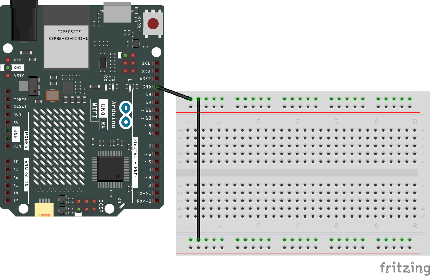
Now, you can ground any circuit by connecting it to any hole on either the top or bottom ground rail!
-
Disconnect your arduino from power (unplug the cable) and wire up the circuit. Refer to the prelab for a reminder on how the circuit diagram corresponds to the physical circuit. Use the same resistor that you computed in the prelab.
Before powering up the circuit, go through the circuit checklist.
-
In your code, create a constant global variable for your LED pin, with value 4. Change all appearances of
LED_BUILTINin your code to this variable. -
Connect your Arduino to the computer and upload your code, verifying that the LED you added lights up instead of the on-board LED.
Get checked off by a TA
-
-
Practice wiring up a button:
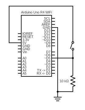
We will implement the switch
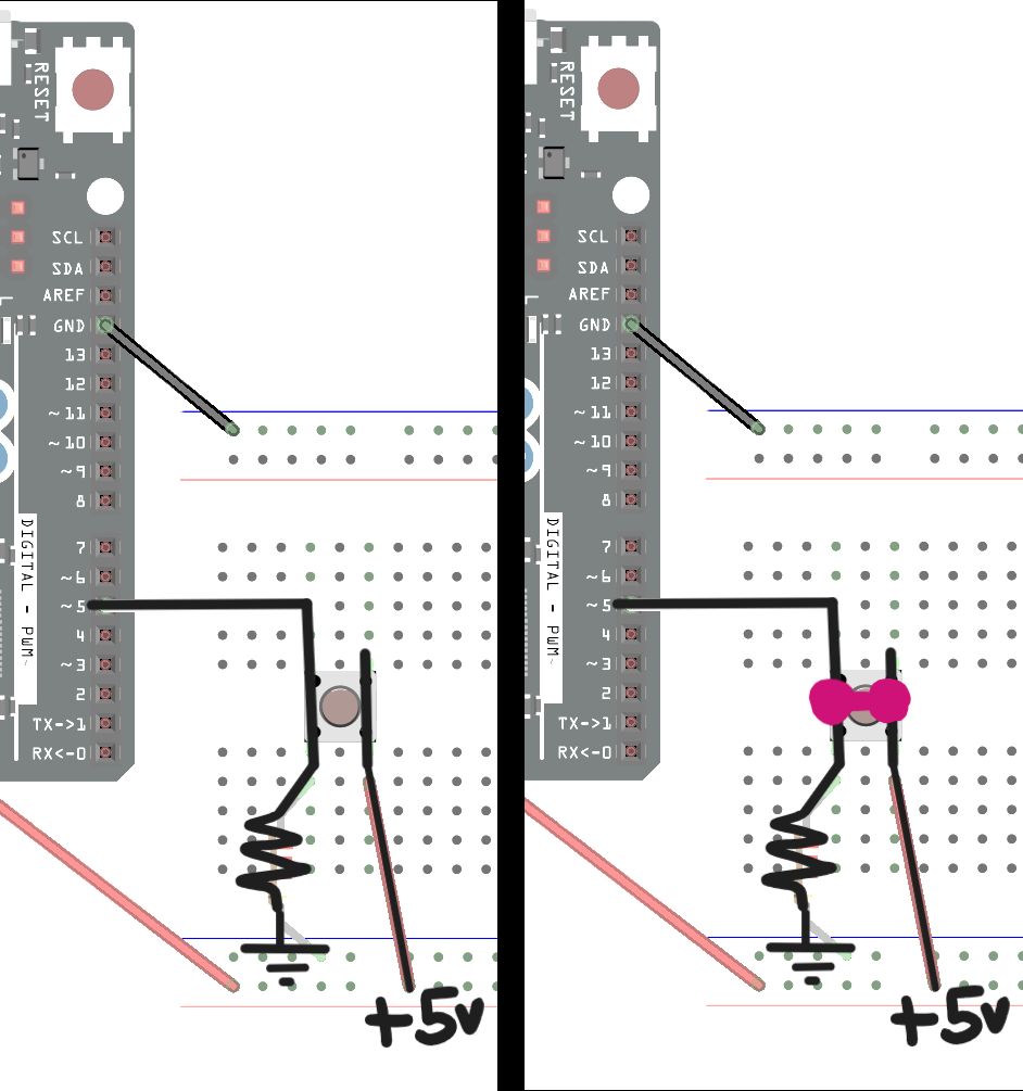
 using a push button. A push button enables a connection between the 5V pin and the input pin when pressed. To do this, a push button is connected like this (the yellow wire is going to pin 5 of the Arduino, the red wire is connected to 5V, and the black wire is connected to GND):
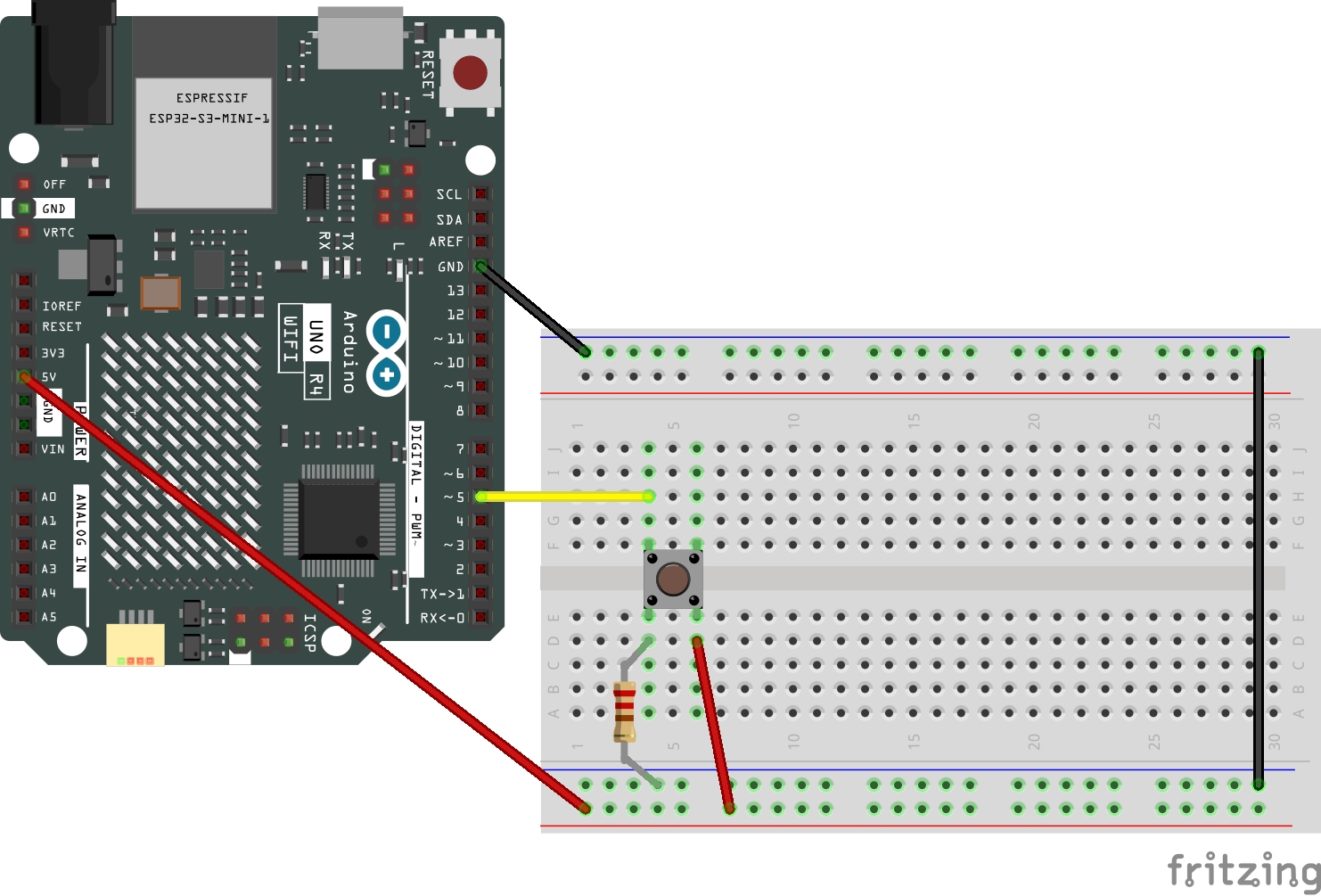
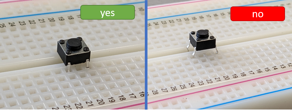
The orientation in which the button is plugged in to the circuit matters. Notice that, on your button, there are two sides that do not have legs attached, and two sides that each have two legs attached. The sides with the legs should sit on either side of the DIP support (the breadboard’s “ditch”).
Why are we wiring up the button this way? When the button is unpressed, the two sets of opposite legs are wired together. This means that, when the button is unpushed, pin 5 of the Arduino is wired to the resistor that goes to ground. The button leg that is wired to +5V isn’t connected to anything else. However, when the button is pushed, all of the legs of the button are electrically connected. This means that current is able to flow from +5v, through the resistor, to ground (this tells us why the resistor matters: we don’t ever want a direct connection from a voltage source to ground!). Since there will be a voltage drop across the resistor, and since pin 5 of the Arduino is at the “top” (higher voltage side) of the resistor, pin 5 would measure a high signal when the button is pressed.
-
Wire up your circuit. Do not use the same resistor as in the breadboard graphic above, but instead use the resistor color codes as a reference to find the 10kΩ resistor.
-
Open the serial monitor by pressing the button at the top of the screen. Some students have had to open the monitor before loading the code, and some students have had to do it after. Often, even if the Serial monitor doesn’t show anything at first, it’s still connected – try running the code below and see if you see an output.
-
Study and run the following skeleton code:
/* * Prints the result of the button press to the serial monitor. */ int BUTTON_PIN = 5; void setup() { Serial.begin(9600); while (!Serial); // Wait for Serial to initialize pinMode(BUTTON_PIN, INPUT); } void loop() { Serial.println(digitalRead(BUTTON_PIN)); } -
Observe the output change as you press and release the button
-
-
Now, implement a binary counter using this circuit:
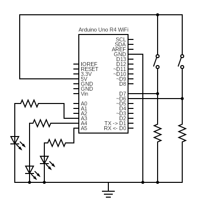
The resistors connected to each of the LEDs have a resistance of 1 kΩ. The resistors connected to each of the buttons have a resistance of 10 kΩ.
Remember that crossing lines are only physically connected when there is a solid dot at the junction of the lines. Otherwise, interpret the wires as crossing over each other without being connected.
-
Each of the 3 LEDs represents a binary digit. The most significant digit is connected to pin 3. As an example, for the LEDs connected to pins A3-A5, refer to the LEDs as
L2,L1, andL0, respectively. IfL1andL0are on butL2is off, this displays011and represents 3 in binary. Wire up your circuit and use the checklist to check it. -
The push button on pin 7 is to decrement the counter, and the push button on pin 6 is to increment the counter. If the decrement button is pushed, the LED binary counter should decrement by 1. If the decrement button is pushed when the counter is displaying a 0 (all LEDs off, representing binary
000), nothing should happen. Similarly, if the increment button is pushed, the LED binary counter should increment by 1, and if it is pushed when the counter is displaying 7 (all LEDs on, representing binary111), nothing should happen. Assume that only one button is pushed at a time. Also assume that the counter starts at 0. -
Start a new sketch (using
Examples > 01. Basics > Bare Minimumgives you skeleton code to start with) and implement the functionality described above. Remember to usepinMode(...)to define pins as inputs or outputs. The input from the buttons can be ready usingdigitalRead(...). -
Upload your sketch to the Arduino and verify if it works. If it does, congrats! Get checked off by the TA, and you are done with the in-class portion of the lab. Otherwise, spend at least 15 minutes debugging with your partner before asking a TA for help. We suggest using Serial.println(…) and
Tools > Serial Monitoras in Step 6 to print debug information.Hint: your first instinct may be to poll
digitalRead(...)for a high signal, making the numbers increment rapidly as long as the button is pushed, rather than checking for the edge where it changes from 0 to 1. How do you detect this change?
-
-
Turn in your work:
-
Save your binary counter sketch as
lab01_bincount. Upload this to the “Lab 1 Code” assignment on Gradescope (include all partner(s) on the submission). We don’t grade your code, but we just want a copy of it (when github classroom fixes their issues, we might switch to it to make this easier…) -
INDIVIDUALLY, complete the Lab 1 writeup assignment on Gradescope.
-