Runtime Monitoring
Last day for on-time checkoff: Tuesday, 11/18 (two weeks)
Prelab due 11/03/25 at 1:00 pm
Writeup due 11/17/25 at 1:00 pm
About
In this lab, you will be given compiled binaries of “air conditioner” software to run on one of your Arduinos. You will be given a reference working binary, and a buggy binary. Your job will be to use the second Arduino to monitor what is happening on the first Arduino (the air conditioner) and use computations on the monitored values to report if/when a safety violation occurs. The runtime monitor will listen to messages sent by the air conditioner and also observe some of the electrical signals being sent to/from the air conditioner. Every time it receives a message, it will check each of the 10 safety properties described in the lab. By the end of this lab, you should understand how a runtime monitor can tap into the interfaces of a running system in order to ensure that it is operating safely.
Lab 8 Rubric
Resources
Lab 8 information doc from prelab
Starter code; includes:
- AC and Monitor hardware check files
- Runtime monitor FSM stencil
- Working AC binary
- Buggy AC binaries
Materials
Included in your kits:
- 2x Arduino UNO R4 WiFi and USB-C cable
- 5 resistors (4 x 625Ω - 1kΩ, 1 x 220 Ω)
- 3 x blue LED
- 1 x yellow LED
- 1 x potentiometer
- 1 x button
- Jumpers/wires
Provided:
- None necessary
Steps
-
As described in the prelab, you will be working with two Arduinos, one that is meant to emulate an air conditioner and one that is meant to monitor the air conditioner. You will be given a working executable to load on your AC Arduino that you will monitor (and observe that there are no safety violations). You will then be given a mystery binary, which is meant to represent an AC that has shipped with faulty software or sensors, and you will use your monitor to figure out which bug the AC has.
-
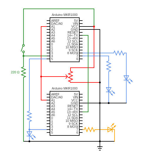
We will use the following circuit (don’t wire the whole thing up yet!). The top Arduino is the AC Arduino, and the bottom Arduino is the runtime monitor. We used blue LEDs for the three LEDs connected to the AC and a yellow LED for the LED connected to pin 7 of the monitor. The resistors in series with the LEDs can be anywhere from 625Ω to 1kΩ.
-
Check that the hardware is working:
-
Wire up the AC circuit (top Arduino, blue LEDs, button, potentiometer). In the starter code, there are a few folders that you will use in different steps in the lab. First, open the
hardware_test_acsketch and upload it to the AC Arduino. Verify that pressing the button and turning the potentiometer causes the Serial monitor output to change accordingly (the potentiometer value should range from about 0 to about 1023). Verify that two of the blue LEDs blinks changes from 0% to 50% to 100% brightness and back. One should flash 0% to 100%. If one or more of these things is not happening, troubleshoot your circuit before moving on. -
Unplug the AC Arduino for now. Now, wire up the monitor circuit (bottom Arduino, yellow LED, connection to potentiometer and blue LED on AC’s pin 3, Serial TX/RX wire). Double-check that ground for the two Arduinos is connected and that the AC Arduino’s TX pin goes to the monitor Arduino’s RX pin (not the other way around!!!). Plug the AC Arduino back in (the hardware check code should still be running on it). Open the
hardware_test_monitorsketch and upload it to your monitor Arduino. Verify that the “cs 1600” message from the AC Arduino is being displayed on the Serial monitor for the monitor Arduino, along with the potentiometer value and AC status LED value. Also verify that the yellow indicator LED is blinking on and off. If one or more of these things is not happening, troubleshoot your circuit before moving on.
-
-
Unplug the USB cable for the monitor Arduino, for now. Load the working binary onto the AC Arduino by following these instructions:
-
Connect the AC Arduino to the computer using the USB cable. Open the Arduino IDE and open the Blink built-in example.
-
Under
File -> Preferences(Arduino IDE -> Settingson Mac), check the “Show verbose output during: upload” box. Be sure to press OK at the bottom to save your preferences.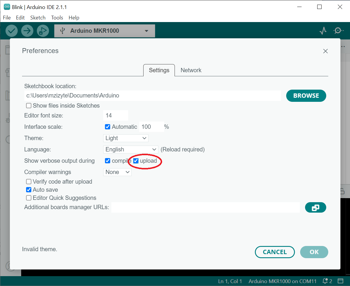
-
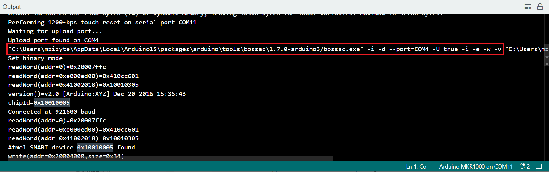
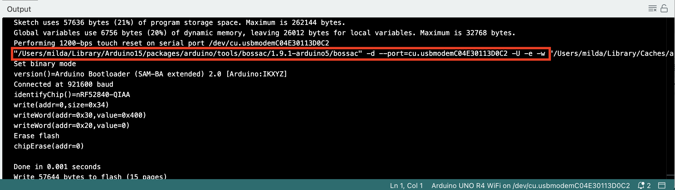
Press the upload button. Once the code is uploaded, scroll up in the IDE terminal to find and copy the upload command (
bossac) up to and including the-U -e -wflags (and possibly others – basically up to the filename), which will look something like below (click image to enlarge if needed). The command might be preceded by “Upload port found” or by “Performing 1200-bps touch reset”:Windows:
MacOS:
-
Exit the IDE. Make note of the full filepath of the
AC_no_bugs.ino.binbinary in thebinariesfolder of the stencil code. Open your terminal (Linux/Mac) or command prompt (Windows) and paste the upload command, followed by the full filepath of the starter binary location, followed by-R, but do not run the command yet. For example, on Windows, your command might look like:“C:\Users\mzizyte\AppData\Local\Arduino15\packages\arduino\tools\bossac\1.9.1-arduino5/bossac” -d –port=COM3 -U -e -w C:\Users\name\Downloads\AC_no_bugs.ino.bin -R
and on Mac like:
“/Users/milda/Library/Arduino15/packages/arduino/tools/bossac/1.9.1-arduino5/bossac” -d –port=cu.usbmodemC04E30113D0C2 -U -e -w /Users/name/Downloads/AC_no_bugs.ino.bin -R
-
Double-press the RST button on your AC Arduino quickly, so that it enters bootloader mode. The LED on your board will fade in and out. Now run the command above so that the binary is uploaded onto the Arduino. If you get a device not found error, make sure that all Serial monitors in all IDE windows are closed. If that fails, close all IDE windows.
-
Observe the AC system working. In particular, verify that pressing the button on and off turns the system on and off. Also observe that one of the LEDs (connected to pin 6 of the AC Arduino) indicates the desired temperature and should change brightness when you turn the potentiometer. One of the other LEDs (connected to pin 5 of the AC Arduino) indicates the current temperature and should eventually increase in brightness if the AC is off and decrease in brightness if the AC is on until it matches the desired temperature. Finally, the last LED (connected to pin 3 of the AC Arduino) should either be on or off at any given time and indicate whether the AC is on or off.
-
-
Implement your monitor: note for this and the subsequent step: this is the last structured lab session, and the due date for this lab is extended, so if implementation or debugging are taking longer than expected, keep in mind that you have the option of also working on this lab later.
-
Open the monitor starter code (
lab8_monitor). -
The only file you will need to change (to update monitor variables and check safety properties) is
monitor_functions.ino. As the prelab said, two properties (properties 2 and 4) have been implemented for you, 2 incheckSysToggleand 4 incheckSysOn. Following the conventions of the prelab monitor FSM,initVars/updateVarsare called after properties are checked in the FSM. When you upload and run this monitor code on the monitor Arduino, you should not get any violations. (A violation would turn off the yellow indicator LED, which serves as a visual cue on the board that the system would be stopped if this were a real device). -
Implement
updateVarsand the rest of the safety properties 1, 3, and 5-8, based on your prelab answers. Run the monitor code on the monitor Arduino and play with the AC interfaces (button and potentiometer). Be sure that the potentiometer is firmly seated in the breadboard and that you are not turning it past its limits, to avoid false positives of violations. When running the provided binary and your monitor, no property violation should occur because the code should be working as intended. Once you are confident that your monitor is correctly monitoring the system in all states, move on to the next step but make sure that you can easily revert to your code from this step. -
Change the check for property 2 so that it will get violated for some sequence of interactions with the Arduino. Once you change the check, verify that the property does indeed get violated using some sequence of interactions with the AC Arduino. The idea is to show that you understand what the property means, how the system is working, and what is necessary for a violation to happen. Once you do this, get this and the previous step checked off by a TA and revert the change.
-
-
Solve the mystery!
-
There are multiple buggy binaries in the stencil code, each of which violates one of the properties 1 and 3-8 at some semi-random point in the code (that is, the violation may not show up immediately). To see this, upload the
bug_prop4.ino.binbinary to the AC and observe that, after a few seconds or so, the monitor shows that property 4 was violated. -
Upload the buggy binary that your TA assigned to you onto the AC Arduino, and run your monitor Arduino. Play with the AC interfaces (button and potentiometer) to solve the mystery of which property the buggy binary violates. Get checked off by a TA, and take note of the buggy binary (letter) and violated property (number) for the writeup. Be ready to justify the violation, by showing the exact messages that caused the violation to trigger. If it is taking you longer than 15 minutes to find the property violation, ask your TA for a hint and review your monitor code. If it takes you longer than 20 minutes after receiving the hint, ask your TA to assign you a different buggy binary.
-
-
Turn in the
monitor_functions.inocode on the Lab 8: Code Gradescope assignment