Sensors, Actuators, and I/O
Prelab due 9/15/25 at 1:00 pm
Writeup due 9/22/25 at 1:00 pm
About
In this lab, you will continue to get experience wiring circuits and writing Arduino code. This lab introduces the analogWrite and analogRead functions and has you explore how to use them with multiple different input and output devices in your kit. By the end of this lab, you should have a deeper understanding of how to manipulate and read voltages in embedded circuits, by use of pulse-width modulation (PWM), Analog to Digital Converters (ADCs), Digital to Analog Converters (DACs), and voltage divider circuits.
Lab 2 Rubric
Resources
Materials
Included in your kits:
- Arduino UNO R4 WiFi and USB-C cable
- Breadboard
- 2 LEDs (recommended red)
- 3 resistors (3: 1kΩ)
- 1 capacitor (100 μF)
- 1 RBG LED
- 1 potentiometer
- Jumpers/wires
Provided:
- None necessary
Steps
Note: during the course of this lab, you will make one graph that you will be asked to discuss in your lab writeup. We suggest making and saving this graph in a Google sheet, shared with you and your partner, so that you can reference it later.
For these and the following labs, we do not show ground explicitly connected to the GND pin of the Arduino, to make the diagrams less cluttered. You should ALWAYS connected the GND pin of the Arduino to the ground rails of the breadboard, as described in Lab 1.
-
Build a circuit to explore a visual representation of PWM:
-
Recall from class that PWM is a way to simulate analog (continuous) output using a digital signal. The duty cycle of a PWM signal can vary from 0% (always off) to 100% (always on):
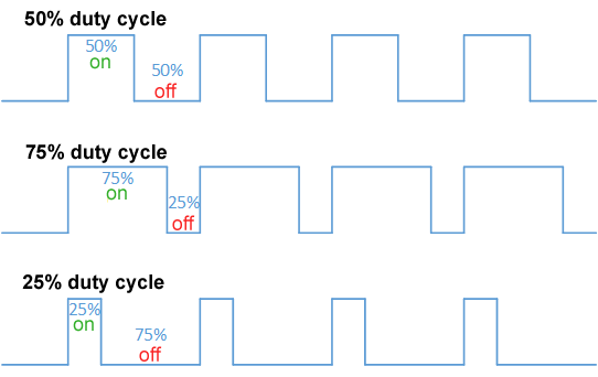
(image from Wikipedia)
-
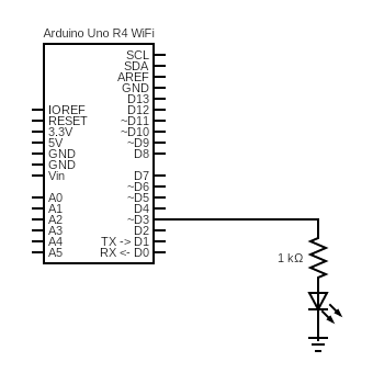
On your breadboard, build the following circuit. We recommend using a red LED for brightness/visibility:
-
In the pre-lab, you read about analogWrite(…). Read the following code and make sure you understand what it does by discussing it with your partner:
/* * Opens serial communication between the Arduino and the computer * Takes in a number 0-255 from the serial monitor and * sets the output PWM duty cycle on LED_PIN to that number */ int LED_PIN = 3; void setup() { Serial.begin(9600); while (!Serial); // Wait for Serial to initialize Serial.println("Ready!"); analogWrite(LED_PIN, 0); } void loop() { if (Serial.available() > 0) { int input_pwm = Serial.parseInt(); Serial.parseInt(); // Ignore null character if (input_pwm < 0 or input_pwm > 255) { Serial.println("Input out of range; ignoring"); } else { Serial.print("Received input of "); Serial.println(input_pwm); analogWrite(LED_PIN, input_pwm); } } } -
Copy the code into a new Arduino sketch. Open the Serial Monitor and then upload the sketch to the Arduino.
-
Play around sending different values through the serial monitor. What happens to the LED? Does it match your intuition?
-
-
To see numerical evidence to back up your intuition, and to explore
analogRead(...), we will use a capacitor to smooth (essentially, average) a PWM signal.-
Think about how you would measure the average voltage output by a PWM pin. One way is to use
digitalRead(...)(check yourself: why notanalogRead?) and average a sample of the results. This might lead to different or even incorrect results based on the sampling frequency, which depends on multiple factors, including how long thedigitalRead(...)takes and how long any computation takes between samples. Imagine if the sampling frequency happened to be the same as the PWM frequency. Then, we would sample the same point of the PWM curve every time, and always measure the same voltage, which would not give us the correct average: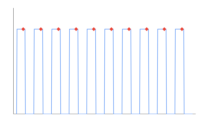
Instead, we will use a circuit component to do some averaging for us.
-
Construct the following circuit:
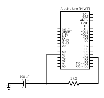
That new symbol
 is a capacitor. Make sure you use the correct capacitor (helpfully, it has the capacitance printed right on the body), and pay attention to its polarity! The anode (positive side) has a longer leg.
If your kit doesn’t have a 100 uF capacitor, you can use a 100 nF capacitor and a 1 mega (not kilo) Ohm resistor. The 100 nF capacitor looks like a ceramic circle with a 104 stamped on it and is not polarized. (The 104 is shorthand to determine the number of picofarads for a capacitor. The the third digit is how many zeroes you add on to the first two digits, so a 104 capacitor is 100,000 pF, or 100 nF. Similarly, a 103 capacitor is 10,000 pF, or 10 nF, and a 681 capacitor is 680 pF).
Optional: why does it work to replace a 100uF capacitor and 1kOhm resistor with a 100nF capacitor and 1MOhm resistor?
Many of the electrical characteristics of RC (resistor-capacitor) circuits a re beyond the scope of this class, because they are more often seen in AC (alternating current, where the current fluctuates as a waveform, as opposed to the DC/Direct Current circuits we see in this class) circuits. There's a lot of cool stuff you can do with RC circuits, and we need mathematical formulas beyond Ohm's law to understand them. However, the key idea behind them is that there's a time factor involved in describing how they work, because it takes time to charge up a capacitor, as you'll see below. If the time factor is too large, it will take too much time for the capacitor to charge up, so the measurements we want to make will take too long, and if the time factor is too small, the capacitor will charge up and discharge too quickly to exhibit the "smoothing out" we're looking for. The time factor is determined by the product of the resistance and capacitance, and 100uF * 1kOhm = 100 nF * 1MOhm, so we're able to swap out both the capacitor and resistor and get roughly the same charge/discharge behavior. Of course, a larger resistor means that the current through this circuit will be decreased, but that's fine for us, since we're not trying to power any actuators. -
A capacitor stores electric energy – a little like a rechargeable battery. When it receives a voltage, it gradually charges up, and when the voltage source is gone, it gradually discharges. For a PWM circuit, that charging and discharging lead to a voltage across the capacitor that resembles the red line here:
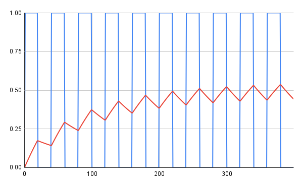
Hence, given enough PWM cycles, the voltage across the capacitor will settle to a small error around the average voltage of the PWM signal. No matter at which point in the cycle you happen to sample the voltage, across the capacitor, it will be close enough to the average voltage of the PWM cycle (for our measurement purposes). Just like our eyes averaged the on-and-off brightness of an LED driven by a PWM signal, we’re using the capacitor to help us see what the average voltage of a PWM signal over time looks like.
-
Write some Arduino code to measure the voltage across the capacitor by calling analogRead(…) on pin
A1. Use the following starter:pwmVal = ____ analogWrite(3, pwmVal) delay(300) // needed for the cap to settle int adc = analogRead(A1) float adc_v = ___ // todo: convert adc (0-1023) to voltage (0.0-5.0) Serial.print(pwmVal) Serial.print(", ") Serial.println(adc_v)Your code should cycle through all PWM duty cycles on pin 3, from 0-255.
-
Run this program on the Arduino and copy the serial output to a spreadsheet. On Google sheets, you can paste comma-separated lists into a single column and then click the clipboard at the bottom-right of the pasted selection and select “Split text to columns.” Graph the curve of PWM duty cycle vs. voltage across the capacitor. Is this the result you expect? Why or why not?
Get your graph checked off by a TA.
-
-
While, in some ways, PWM approximates a continuous (analog) output signal, it is important to understand the difference between a PWM output and an analog output. Construct some circuits to see the difference between the two in practice:
-
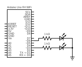
First, construct the circuit below. We suggest red LEDs for brightness/visibility:
-
Using analogWriteResolution(…), set the analog write resolution of the Arduino to 8 bits. This will make things consistent with the DAC pin we will use in the next step. Write some Arduino code to drive each of the LEDs with a PWM with 25% duty cycle (input of 63 to
analogWrite(...)) -
Upload your code to the Arduino. You should observe both LEDs glowing at the same, partial brightness. If this doesn’t happen, your LEDs might be deficient, or you are calling
pinMode(...)before callinganalogWrite(...), which you shouldn’t do (sincepinModeis used for GPIO, not PWM). -
Unplug the Arduino and change the pin driving one of the LEDs to the DAC/A0 pin:
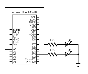
This pin has a Digital to Analog Converter, which means that
analogWrite(...)outputs a desired voltage between 0V and 5, instead of a PWM signal. -
Update your code from step 3b to drive the LED with the
A0pin, at quarter-voltage (input of 63 toanalogWrite(...)). Except for changing the pin number, nothing else about your code should change. -
Upload your code to the Arduino. What do you observe? Why do you think this happened? Discuss it with your partner or ask a TA for a hint. You will be asked to answer this question in your own words for the lab writeup.
-
-
One of the powerful things about microcontrollers is that you can write code that makes the output of some components respond to the input of other components. This provides more flexibility and functionality than hooking up the components directly in a circuit. You’ve already done a basic version of this in Lab 1, where you read a button input and controlled some LEDs. Now, you will use a potentiometer to control an RBG LED, which will involve some slightly more complicated code.
-
You will be using a potentiometer for this step. To understand how a potentiometer works, first recall this voltage divider circuit from the prelab (you do not have to connect this circuit):
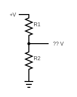
In the prelab, you defined a formula for the voltage at the point
?? Vin terms ofR1andR2. Hence, by choosing values ofR1andR2, this circuit can be used to divide the supply voltage to whatever lower value you want. BecauseR1andR2are fixed for any specific circuit, however, this divided voltage will also be fixed.A potentiometer works on the same principle. While different potentiometers work in different ways, conceptually, you can imagine it internally changing the values of
R1andR2as its dial is turned. This means that, a potentiometer can be set to output any voltages in between 0 and its supply voltage while the circuit is on. -
Armed with this knowledge, you can work with the following circuit. Construct it on your breadboard:
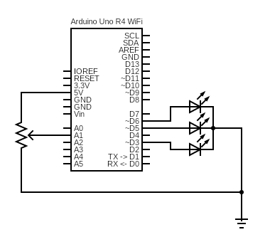
Keep in mind that crossing lines are only connected if there is a solid black dot at the junction. In this diagram, the button/10k resistor should only be connected to pin 2 (and 5V and ground), not the other pins.
The potentiometer symbol, fittingly, looks like a resistor with an arrow pointing to it, to symbolize the variable internal resistance ratios. Your potentiometer may look like a blue square with two legs on one side and one leg on the other. The potentiometers are not polarized, meaning that, for the two legs on the same side, you can choose one to connect to ground and then connect the other to 5V. The leg on the side by itself should get connected to the analog pin of the Arduino. If you have a potentiometer with all of the legs in a row, the middle one should get connected to the analog pin of the Arduino. You might need to place the potentiometer at an angle to your breadboard so that each leg has its own column of holes.
Instead of using three separate LEDs in this circuit, use your RBG LED. It looks like a white LED with four legs. Yours are common cathode, which means that the cathode (longest leg) should be connected to ground. The other four legs control the red, blue, and green outputs of the LED and should each be connected to a different resistor and Arduino pin.
-
Write some code that changes your LED from blue, to purple, to red, to yellow, to green, to teal, back to blue as you turn the potentiometer (where you start and end this cycle doesn’t matter, as long as the whole progression is there in order). Use
analogRead(...)to read in the values of the potentiometer, and useanalogWrite(...)to send a PWM signal to each channel on the LED.
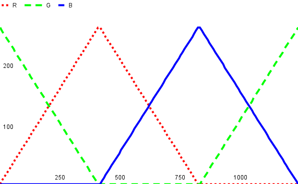
The graph above is an approximation of what the pin output for each leg of the LED should look like as the potentiometer changes in value. One channel of the LED should be off at all times, and the duty cycles of the other two should sum to 255 to maintain a constant brightness. For example, when changing from blue to red, the green LED will be off, and the duty cycles of blue and red will change from B=255, R=0 for completely blue, to B=127, R=128 for purple, to B=0, R=255 for completely red, with intermediate values computed to make a smooth transition. Talk through how you will write this code with your partner, and ask your TA for a hint if needed. Hint: you read about the map function in the prelab. Since you’re reading and writing integers, it may be useful to use this function to cut down on the amount of math you have to do.
-
Upload and run your code on the Arduino. Debug your circuit and code. Hint: if one or more colors of the RBG LED don’t seem to be working, verify that your LED is functional by writing code that turns each one on individually (writing a PWM duty cycle of 255 to one pin and 0 to the other two).
-
Add an interrupt that toggles the LED betweeen on and off when the button is pushed. See the Arduino
attachInterruptdocumentation for details. When the LED is on, the potentiometer should still be able to control its color, so think about what code belongs in the ISR and what code belongs inloop.Note: for reasons we’ll discuss in lab 3, Serial printing doesn’t work in ISRs. If you need to check if an interrupt got called, you can either use the debugger or set some sort of global variable that gets printed in the
loop. -
When you’re confident that your circuit works, get it checked off by a TA. You now know how to use
analogRead(...)andanalogWrite(...)to interact with input and output components using code, and have gained experience using an interrupt to detect changes in digital iunput!
-
-
Turn in your work:
-
Save your code from step 4d and name it lab2.ino. Upload this to the “Lab 2 Code” assignment on Gradescope (include all partner(s) on the submission).
-
INDIVIDUALLY, complete the Lab 2 writeup assignment on Gradescope.
-