Networking and communication
Last day for on-time checkoff: Tuesday, 11/4
Prelab due 10/27/25 at 1:00 pm
Writeup due 11/10/25 at 1:00 pm
About
In this lab, you will explore different ways microcontrollers can interact with each other, using both wired and wireless communication. You will write your own software UART to build understanding of how serial communication works. You will also use the BLE (Bluetooth Low Energy) capabilities of the Arduino Uno R4 to form a distributed system with other devices in the class. By the end of this lab, you should be comfortable with using your Arduinos to communicate with other devices.
Lab 7 Rubric
Resources
Materials
Included in your kits:
- 2x Arduino Uno R4 WiFi and USB cable
- Jumpers/wires
Provided:
- None necessary
Steps
Note: in the past, we’ve had issues with Bluetooth interference for this lab. To help with this, disable Bluetooth on your personal devices (phones etc) for the duration of the lab, if possible.
-
Download or clone the starter code. Install the ArduinoBLE (by Arduino) and Crypto (by Rhys Weatherley) libraries through the Arduino IDE. Step 2 does not require these libraries, so you can start working on it while the libraries install.
-
Your Arduino has built-in UART serial communication that you can use to send data between two Arduinos. To use this functionality, we would use the onboard TX and RX (D1 and D0) pins and use the same syntax as
Serialcommunication with the computer, replacingSerialwithSerial1(e.g.Serial1.begin()). You will make use of this feature in lab 8. However, for this lab, we will DIY a software UART that works on any* pins (*for the receiver, the pins have to support digital interrupts).-
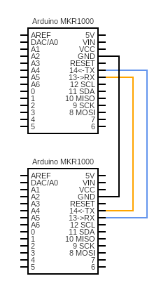
Wire up the following circuit. Be sure to connect the GND pins of both Arduinos to each other!
-
For this step, work with the
lab7_uartsketch from the starter code. Take a few minutes to review the code.If the line
#define SENDERis present inlab7_uart.ino, the device will function as a SENDER. It is going to send a pre-defined image of a monster (an array of threeuint32_ts – a format the onboard LED matrix understands) via theoutPin. We’ve taken care of theloopSendercode, which takes themonsterarray and splits it up into 18 bytes of data (as diagrammed below, with the first byte sent in each group being the array index), loads it into a circular buffer, and then callsuartSendwhile it removes every item from the buffer.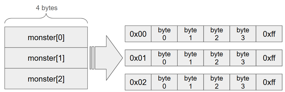
If the line
#define SENDERis commented out, the device will function as a RECEIVER. It uses an interrupt attached to theuartReceivefunction to detect the UART start bit (a change from HIGH to LOW in the input signal), receive a byte, and load it in a buffer. Once it receives 6 bytes (array index byte, 4 bytes to reconstruct theuint32_t, and the end byte), it uses the computation we’ve given you inloopReceiverto make sure the 6 bytes have the expected format. It then updates the frame that it should display on the onboard LED matrix.Note that the use of
#define SENDERis a bit of an unorthodox approach. It’s a consequence of the sender and receiver both using circular buffers, so we’re structuring the code this way so that you only have to edit the buffer file in one place. A better project structure would be to make the buffer code into a library (or, outside of the Arduino framework, a file that gets compiled separately and linked) and to create separate sketches for the sender and the receiver. -
Complete the TODOs in the
uartReceiveanduartSendfunctions according to your prelab logic. Also complete the indicated functions inbuffer.ino. -
You can connect both Arduinos to one computer, or use two different computers. If you are using the same computer, you can switch between Arduinos by changing the port under
Tools -> Port. You will have to do this even if you have multiple IDE windows open. Notice also that the serial monitor changes which Arduino it is receiving data from based on which port is selected – this sometimes even happens in both IDE windows. When you upload the code, make sure that one device gets code with#define SENDERpresent, and the other device gets code with it absent Once the code is running, you should observe that a monster appears on the receiver’s LED matrix. It’s OK (and expected) if the image flickers a bit – this is due to the LED matrix code depending on an interrupt, which gets pre-empted by the GPIO interrupt we have enabled for the UART. Once you have the monster, get checked off by a TA. -
Inject some bit-flip errors by replacing the line
digitalWrite(outPin, HIGH)inuartSendwithdigitalWrite(outPin, HIGH_BITFLIP). Upload the sender code (no need to change the receiver), remembering to select the correct Arduino and to include the#define SENDERline, and press the receiver’s reset button.HIGH_BITFLIPis defined inlab7.hand depends on the signal read in by the unconnected A2 pin, which will be sensitive to electric interference. You can observe the effects by moving the sender Arduino around closer and farther away from sources of interference, such as your hand, the other Arduino, or your computer. Press the reset button on the receiver and observe whether you can see the effects of theuartReceivefunction rejecting messages with bit flips.Now amp up chaos by plugging in an unconnected wire into the A2 pin, which will make it more sensitive to interference. Continue to press the reset button and talk about your observations.
-
-
Now let’s collect some more monsters! For this step, you will need your two Arduinos, but you should disconnect the circuit from step 2, so that the Arduinos are communicating wirelessly. As described in the prelab, you will implement a “home” device, which has access to encrypted monsters, and a “roam” device, which will send keys to the “home” device so that it can decrypt its monsters. We will work with the
lab7_homeandlab7_roamsketch folders.Note: Because the Bluetooth module is actually on the ESP32 microcontroller instead of the RA4M1, there are some dependencies between the two devices when initializing/resetting. The starter code has a workaround for this that resets the ESP32 module if necessary, but this might cause the device to temporarily lose serial connection with your computer. If this happens, close just the serial monitor (not the whole IDE!), check the port via the Tools menu, re-open the serial monitor, and even if you don’t see anything on the Serial monitor, send any character (where it says “Message (Ctrl + Enter to send message…”) to get out of the setup loop that waits for serial communication. You’ll have to send a character through serial every time you restart the device.
-
Decide on a 16-character password and special home device name, and update both
.hfiles where indicated with the “TODO” annotation. We have given you the code that implements the following sequence diagram from the prelab in thehomeInit,checkInbox, androamInitfunctions (found in the respective_ble.inofiles). Take some time to locate where each step in the sequence diagram is implemented in the code and to talk about the use of the BLE functions, which will help you in subsequent steps.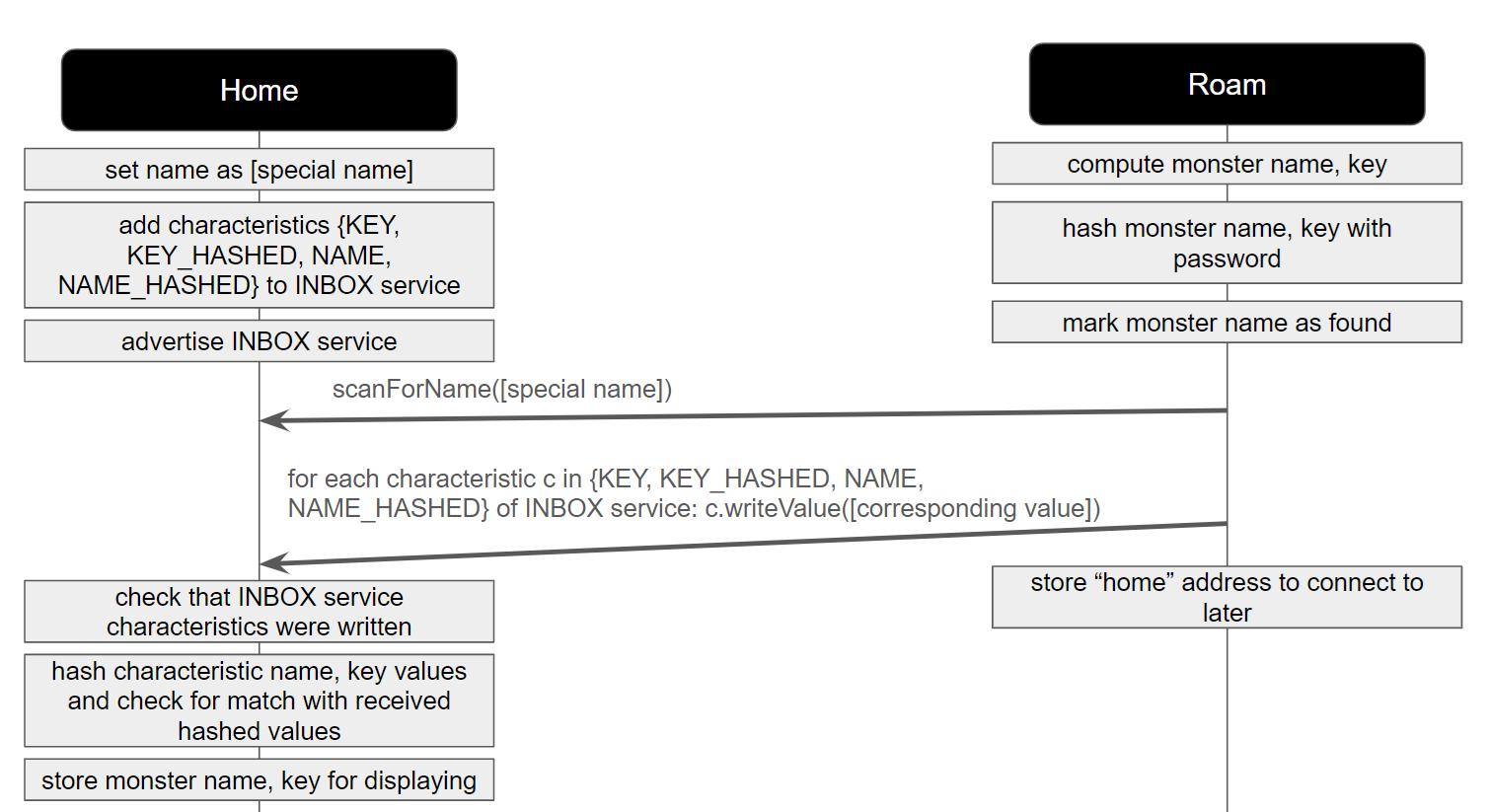
-
The home device should decode each monster before displaying it by XORing the decoded monster with its key (this is basically how decryption/encryption algorithms work, but with more complicated/mathematically secure operators!). Find the “TODO” annotation in
home_utils.inoand perform this computation. Upload the code onto the Arduinos. Open the serial monitor for the home device, and note the command-line interface that allows you to display monsters by inputting a number. Input 0 on the serial monitor and observe your first captured monster!A note on resetting the boards: the communication between the devices is set up such they use the sequence diagram above as an initialization step. To re-run and test code after you’ve made changes, it will be necessary to reset both devices so that they can perform the initialization. Remember to re-establish connection with the serial monitor as described above.
-
The following sequence diagram runs after the initial pairing (once the home device has received a monster from its local roam device). The home device wants to advertise that it has a monster available for any remote roam devices to connect. Find the “TODO” annotations in
home_ble.ino. Implement the steps of the following sequence diagram. Note that similar steps exist in the first sequence diagram, so you would have found example uses of almost all of the relevant BLE functions as you read through the code we gave you. To set the value of a characteristic, you can usewriteValue, e.g.outboxKey.writeValue. You will also have to change the properties of theoutboxKeycharacteristic (at the top ofhome_ble.ino) to match your prelab.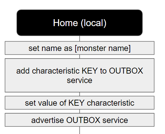
One way to test that the initialization worked is to wait for the home device to initialize and then use your phone to check for available Bluetooth devices (if you are in the lab room, remember to turn off your phone Bluetooth again if possible). You can also initialize both devices, and then upload the
ArduinoBLE -> Central -> PeripheralExplorerexample to the board that was running the roam code. This code will display the names of all of the devices it has found on the serial monitor as well as their advertised characteristics. Once you have your home device initialized, get checked off by a TA! Steps c and d can get checked off at the same time, so start on the next step while you’re waiting. -
Implement the functionality of the local roam device in the function
scanForMonstersinroam_ble.ino, according to the third sequence diagram from the prelab (refer to your answers to remind yourself what role A, B, and C are playing). Notice that you don’t have to write any code for the home device for this step, since the functionality to check the inbox and store the monster is the same as in step 3a.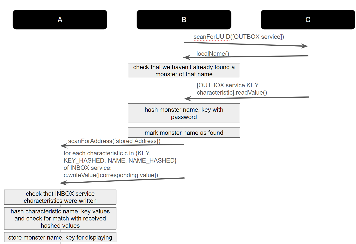
* We provide
addMonster/hasMonsterhelper functions inroam_utils.ino. Once you find a monster, mark it as found usingaddMonsterin order to subsequently ignore devices advertising that monster.* Similar to
connectByName, we have a wrapper function calledconnectByAddressthat scans for a specific BLE device, connects to a peripheral, and returns it for processing. We also have a wrapper function forBLE.scanForUuidspecifically for connecting to theOUTBOXservice. You’ll need to complete a TODO in that function to ignore monsters that you’ve already found.* To get the characteristic of a peripheral that you’ve connected to, use
[peripheral].characteristic(). Notice that this characteristic can be passed to our helper functiongetBLEIntValue.The TAs will be running a device that has the key for a special TA monster. If your code is correct, you should be able to collect this monster almost immediately when you run the code. Once you collect this monster, get checked off by a TA.
-
Wait for more groups to finish this step, so that you can collect more monsters!
-
-
Even though ArduinoBLE doesn’t provide a means of “pairing” devices, the design of our sequence diagrams was meant to ensure that the roam devices could read keys from all other home devices, but the home devices would only accept data from their own roam devices. If you have time, discuss the security implications of this distributed system. You will be asked about these in the lab writeup.
-
Why does the roam device hash every message with a password when communicating with the home device and why are the INBOX attributes write-only? What could go wrong in terms of security if we didn’t do one or both of these things? Think about how an adversarial actor might compromise the integrity of data on the home device in the worst case. For the write-only case, it might help to think outside of the box – for example, what if the home device were restarted?
-
Think about (don’t implement) how you could change how your roam device interacts with remote home devices so that their availability is compromised. Would you be able to prevent other roam devices from accessing data on some home device?
Similarly, how could you be adversarial in setting up the home device? Don’t just think about putting an incorrect key value in the OUTBOX. What else can the home device do to mess with the home devices?
-
-
If you have time, explore the WiFi capabilities of the Uno. Especially if you will be using WiFi for your final project, get your device registered to the Brown network using these instructions. You can find the MAC address of your device by running the
ScanNetworksexample sketch under the WiFiS3 built-in examples (no need to install any libraries here; these examples come bundled when you installed the software for the R4 in lab 1). You do not need to be connected to any networks to run that example. Take a look at the other examples, which are documented here. Specifically, run the NTP client example and observe the Arduino connect to an NTP server to get the time.Note: if you are trying to connect to a website using SSL (like a website that requires https), you will likely need to fetch and upload the SSL root certificate for that website. You can easily do this using the “Upload SSL Root Certificates” tool under the Tools menu.
Another note: BLE and WiFi use the same antenna, so you cannot have one Arduino use BLE and WiFi at the same time. We have not tested if it’s possible to disable WiFi and enable BLE and vice versa in the same program. If you want to use both WiFi and BLE in your project, one approach is to have two Arduinos, one using WiFi and one using BLE, with a physical (Serial/UART) connection.
-
Zip up both sketch folders and turn the code into the Lab 7: Code Gradescope assignment.