Embedded Design and Engineering
Last day for on-time checkoff: Tuesday, 10/21
Prelab due 10/06/22 at 1:00 pm
Writeup due 10/20/22 at 1:00 pm
About
In this lab, you will translate requirements for a game into a Finite State Machine (FSM) description of the game implementation. You will then implement the FSM to run on your Arduino, to produce a game that is played with a physical gamepad and displayed on an LCD screen. By the end of this lab, you will have used a traceability matrix to map behavioral requirements to FSM transitions guards and behaviors and have practiced creating both FSM transition descriptions and code to match an FSM.

Lab 5 Rubric
Resources
Materials
Included in your kits:
- Arduino Uno R4 WiFi and USB cable
- 1 breadboard
- 4 1MΩ resistors
- 1 10KΩ resistor
- Jumpers/wires
Provided:
- Materials for gamepad
Steps
-
Construct a capacitive-touch game controller out of tape, cardboard, and foil. While you are waiting for materials to come around to you for this step, work on Steps 2 and 3.
-
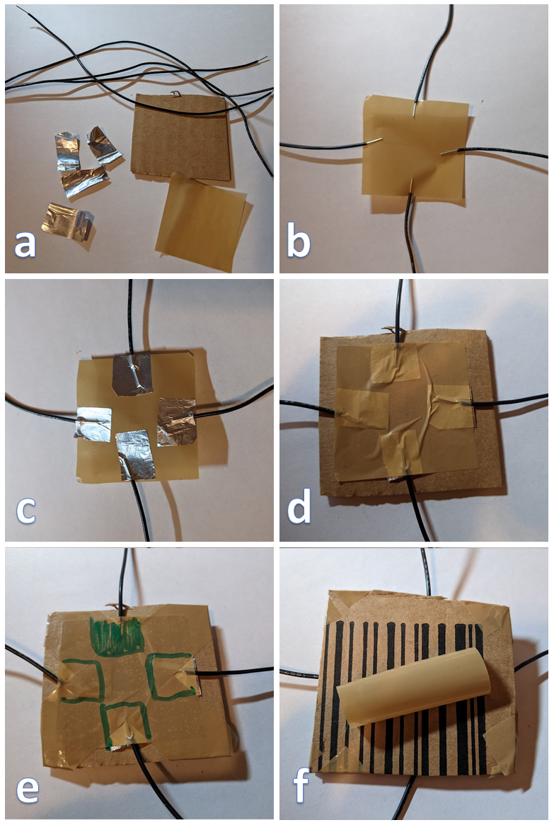
Obtain the following materials: four pieces of wire, about 6” (15cm) long with ends stripped (you should be able to use the wires/stranded jumpers in your kits); four squares of aluminum foil, measuring about 0.5” (1cm) per side; one square of packing tape; one square of cardboard the same size or slightly larger than the tape. (Optional) also obtain a piece of tape (length slightly greater than the diagonal of your cardboard square) cut in half lengthwise, for step e, and a short piece of tape, for step f.
-
Place the square of tape sticky-side up. Stick one end of each wire to the center of each edge of the tape, such that the exposed metal is entirely within the square.
-
Stick a square of foil over each wire end on the tape. Take care that none of the squares of foil touch each other.
-
Stick the piece of tape onto the cardboard square, such that the wire ends and foil are sandwiched between the tape and cardboard.
-
(Optional) secure the controller with more tape and use a permanent marker to indicate where the foil squares are. Here, we used one long strip of tape cut in half lengthwise, and placed each piece diagonally across the square to make an “x,” folding the tape over the edges of the cardboard. We also colored in one of the foil indicators, so that we can orient the square.
-
(Optional) roll up a piece of tape so that the sticky side faces out, and secure it to the back of your controller, so that you can stick the controller onto your table for stability. We recommend doing this step after wiring up your circuit.
-
-
Compare your state chart transition table from the prelab with your partner’s, and resolve any discrepancies. Working with your partner, answer the following questions (in the past, we’ve had students fill out a traceability table, but this took a significant chunk of the lab. This year, we’re asking you to talk through two requirements in some detail, to get a sense of what it means to check a box in a traceability matrix. You can view a partial example traceability matrix here). Note that if you’re working off of an older copy of the prelab document, the requirement numbering is off. You can see the latest version of the prelab document here.
-
What would it mean if the R-3A,B,C columns did not have any boxes checked off in the traceability matrix?
-
Which state(s) and transition(s) satisfy R-9 and why?
-
Which state(s) and transition(s) satisfy R-0 and why?
Get your answers checked off by a TA. While you’re waiting, wire up your circuit.
-
-
Wire up the following circuit.
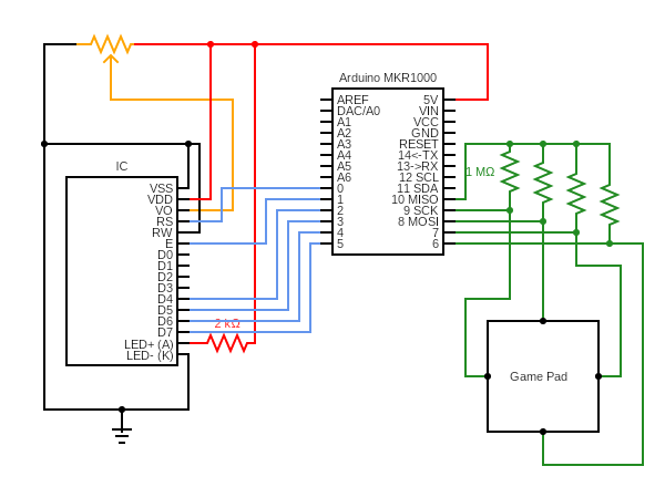
For wiring up the gamepad, it does not matter which wire of the gamepad goes into which of Arduino pins 6-9. You will configure this in code. We suggest using the one of the red + rails of the breadboard to connect pin 10 to the resistors connected to pins 6-9. Because the resistor legs are uncovered metal, take care to make sure that they are not touching each other, which may cause a short between two Arduino pins.
-
Clone or download a zip of the Lab 5 starter code. Open the
lab5folder and open thelab5.inofile in your IDE. In theLibrary Manager(Tools -> Manage Libraries), install the “CapacitiveSensor” library if it is not installed already.The first time you build this code, you will see a compilation error for
CapacitiveSensor.h. Open this file in an editor, and paste in the code below towards the top of the file. This is because the library has not been updated for RA4M1 boards. The code uses bare-metal programming to drive some pins as efficiently as possible. The 2024 course staff figured out what to write here according to the datasheet!#if defined(ARDUINO_UNOR4_WIFI) || defined(ARDUINO_ARCH_RENESAS) // Define alternatives for Renesas RA4M1 (Arduino Uno R4 WiFi) #define PIN_TO_BITMASK(pin) (digitalPinToBitMask(pin)) #define PIN_TO_BASEREG(pin) ((volatile uint32_t*) portOutputRegister(digitalPinToPort(pin))) // For Renesas RA4M1 architecture used in Arduino Uno R4 WiFi #define IO_REG_TYPE uint32_t #define IO_REG_SIZE uint32_t #define DIRECT_READ(reg, mask) ((*((reg) + 1) & (mask)) ? 1 : 0) #define DIRECT_MODE_INPUT(reg, mask) (*(reg) &= ~(mask)) #define DIRECT_MODE_OUTPUT(reg, mask) (*(reg) |= (mask)) #define DIRECT_WRITE_LOW(reg, mask) (*(reg) &= ~(mask << 16)) #define DIRECT_WRITE_HIGH(reg, mask) (*(reg) |= (mask << 16)) #endifOpen the Serial Monitor, and upload and run the code on your Arduino.
-
On the serial monitor, you should see “Capacitive sensing:” and then four values, preceded by 6, 7, 8, 9. Decide on an orientation of your gamepad (i.e. decide which side is “up”). Press your finger to the gamepad sensor that you decided corresponds to “up”, and observe which of the numbers goes up on the Serial Monitor. What threshold do you observe such that values under that threshold mean the gamepad sensor is not pressed, and values above the threshold mean that the sensor is pressed? Change the corresponding values under the comment
LAB STEP 4bof the code such thatcap_sensors[UP]is one of 6, 7, 8, 9 corresponding to the value you observed changes, andthresholds[UP]corresponds to the threshold you decided. Repeat for the other three sensors. -
Comment out the
calibrate()function call under theLAB STEP 4bcomment and uncomment thetest_calibration()function call under theLAB STEP 4ccomment. Upload and run your code. Observe the Serial monitor: it should display nothing when no sensors on the gamepad are pressed, and display “X pressed” when sensor X is pressed, where X corresponds to UP, RIGHT, DOWN, or LEFT. If one or more sensors is miscalibrated, repeat Step 4b or check your circuit. -
Comment out or remove the
calibrate()andtest_calibration()lines. Your code is now set up to take inputs from the gamepad.A note on the code: a lot of the underlying behavior (setting up the matrix, storing the snake, reading sensors) is abstracted away into
snakeUtils.inoandcontrollerUtils.ino. While you do not need to read or modify these files for this lab, you may find it helpful refer to this file as well aslab5.hto see how certain types (likefullState,orientation, andxyo) are defined and used. If your course project will use capacitive sensing or the LED matrix, you should take a look at the code on your own time for a starting point on how these components are set up.
-
-
Implement three helper functions (under the comments reading
LAB STEP 5) that correspond to your answers to prelab Q2. -
Under the comment reading
LAB STEP 6, initialize all of the variables according to prelab Q3. After doing this, uncomment the line that starts withfs = updateFSM(...so that the FSM can get updated on every iteration ofloop. -
Under the comment reading
LAB STEP 7, implement the FSM that you and your partner decided on in step 2.The
updateFSMfunction takes a struct that holds the current FSM state and state variables and the three inputs described in the prelab. Just as described in the prelab, the order of operations is: 1) check the transition guard; 2) output something if needed (snake util output functions or Serial); 3) modify the state variables (if needed); and 4) return the next state.You should not deviate from the conventions in the starter code (which you will be graded on for this lab), namely that the FSM is implemented as a
switch...caseon the state input, where eachcaseblock checks the transitions and performs actions if the transition needs to be taken. Some of the transitions from the prelab have been done for you, as a reference. The code is set up to return the current state for situations when a transition is not taken.-
Following the examples in the code, comment each transition guard checking with the annotation of the transition, e.g.
// t a-bfor a transition going from state a to state b (the state numbers of a and b suffice, rather than the full state name). -
With your partner, go through this code and check that each transition defined in the table of prelab step 4 has an annotation in the code.
-
Upload and run your code, and try playing the game. Even if the code does not work exactly correctly, get it checked off by a TA now.
-
Spend up to the end of lab time debugging your code and state chart, but do not worry if you do not get it fully working – the point of the next lab is to test this code, so keep your circuit and make sure both partners have a copy of the code.
-
-
Turn in your work:
-
Save your code as “lab5.ino”. Upload this to the “Lab 5 Code” assignment on Gradescope (include all partner(s) on the submission). You do not have to upload the helper files we gave you. It is important to turn the code in so that you can earn the code style points from the rubric.
-
INDIVIDUALLY, complete the Lab 5 writeup assignment on Gradescope.
-